Video‑based Dynamic Mesh Coding (V‑DMC)
V‑DMC specifies the syntax, semantics, encoding and decoding of dynamic triangular meshes using a video‑based approach. It targets volumetric humans, avatars and deformable objects, enabling efficient compression, lossless/lossy modes, and real‑time playback across AR/VR, telepresence, volumetric video and immersive media workflows.
Public Reference Software
V-DMC Test Model — mpeg-vdmc-tm
The V-DMC Test Model is the official open-source implementation of ISO/IEC 23090-29. It demonstrates the full encoder/decoder workflow including basemesh subdivision, displacement and attribute coding, atlas generation, and video integration. The repository provides configuration examples and validation scripts for reproducible evaluation.
Repository: github.com/MPEGGroup/mpeg-vdmc-tm
Reference codecEncoder/DecoderTest ModelMesh Metric Software — mpeg-pcc-mmetric
The Mesh Metric software is used for objective evaluation of geometry and texture fidelity in reconstructed dynamic meshes. It computes Hausdorff and per-vertex distances, as well as image-based metrics for texture accuracy, and is employed in MPEG Common Test Conditions to benchmark compression performance.
Repository: github.com/MPEGGroup/mpeg-pcc-mmetric
MetricsEvaluationCTCMPEG 3D Graphics Renderer — mpeg-3dg-renderer
The MPEG 3D Graphics Renderer provides reference visualization for static and dynamic meshes and point clouds.
Repository: github.com/MPEGGroup/mpeg-3dg-renderer
RendererVisualizationPlaybackAll repositories are maintained by ISO/IEC JTC 1/SC 29/WG 7 under the official MPEGGroup GitHub organization. They are available for research, conformance validation, and interoperability testing.
Technology at a glance
What is a dynamic mesh?
A dynamic mesh is a 3D surface that evolves over time: per‑frame geometry, connectivity and attributes (e.g., colours, normals, UVs) describe moving/deforming objects such as humans and animated characters. Texture mapping and displacement are used to represent fine details.
Acquisition & creation
Dynamic meshes can be captured using RGB‑D/ToF sensors, photogrammetry pipelines, or synthesized via AI/computer‑vision pipelines that infer geometry from multi‑view imagery. V‑DMC is agnostic to the source as long as per‑frame meshes and attributes are provided.
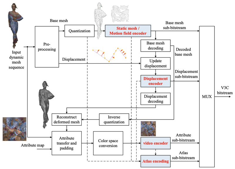
Encoder pipeline
Encoders perform mesh preprocessing (simplification, parameterization, segmentation), basemesh coding (static + motion via the Annex H wrapper), displacement processing (lifting transform, quantization, video or arithmetic coding), and attribute processing (texture transfer, padding, attribute video coding). Sub‑bitstreams are encapsulated into a V3C bitstream.
Basemesh & displacements
Connectivity in each frame is obtained by subdividing a basemesh for that frame; the basemesh may vary over time. Per‑frame displacements (often normal‑aligned) refine the subdivided geometry relative to that frame's basemesh. Supported subdivision schemes include Midpoint, Loop, Normal, Pythagorean and edge‑adaptive. Displacements may be packed into rectangular slices or coded via arithmetic coding; both local and canonical coordinates are supported, including a 1D normal‑only option.
Atlases & parameterization
UVAtlas and OrthoAtlas methods parameterize surfaces into temporally‑stable 2D tiles that pack geometry and attribute signals into video frames for compression using mature video codecs (e.g., HEVC/VVC).
Attributes
Texture and per‑vertex attributes use attribute transfer, padding and occupancy‑aware RDO. Multiple atlases/components are supported, with either video‑based or arithmetic coding depending on profiles.
Encoder structure
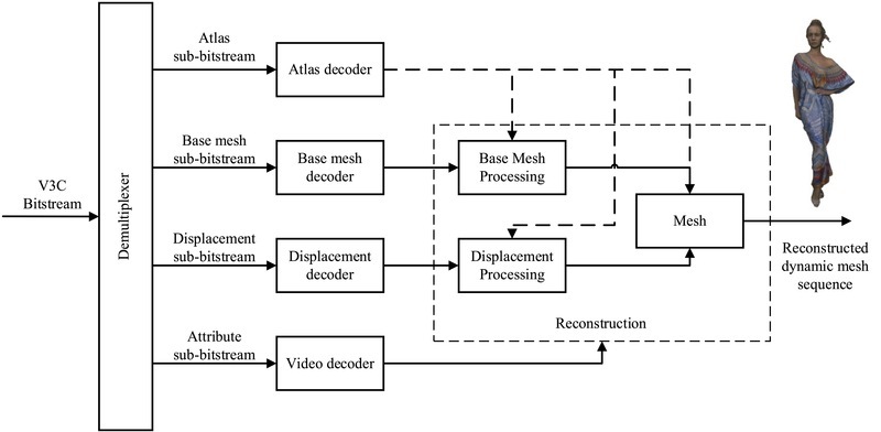
Decoder structure
Syntax & Semantics
Bitstream organization
V‑DMC follows a V3C‑style structure with coded sequences split into Groups of Frames (GOFs) and per‑timestamp access units. Components have non‑coding NAL units (ASPS, BMSPS, DSPS, SPS, AFPS/BMFPS/DFPS/PPS, SEI) and coding NAL units (ACL, BMCL, DCL, VCL).
Profiles, tiers & levels (PTL)
Toolset profiles: Toolset0 (highly constrained, broad device reach) and Toolset1 (fewer restrictions, higher efficiency). Codec group profiles: declare the video/non‑video codecs in use (e.g., HEVC Main 10 for video, Annex H basemesh wrapper). Reconstruction profiles: recommend algorithms used after decoding to reassemble the final mesh.
Conformance points
Conformance point A (decoder outputs): bit‑exact decoding of each sub‑component (atlas, basemesh, displacements, attributes). Conformance point B: reconstructed mesh after recommended reconstruction; bit‑exactness is not required, but following the reconstruction profile guarantees quality targets.
Supplemental Enhancement Information
SEI messages enable optional tools: zippering (distance, index, border‑connect), LoD extraction, submesh distortion flags, and tile/submesh mapping, improving visual continuity and diagnostics.
Performance & evaluation
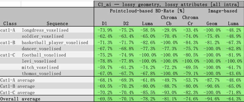
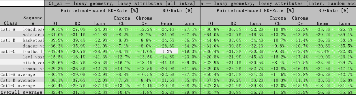
Test conditions (CTC)
Evaluations follow V-DMC Common Test Conditions (CTC) with three modes: C0 lossless, C1 All-Intra (AI), and C2 Random-Access (RA). Test content includes humanoid-centric dynamic sequences (e.g., longdress, soldier, basketball, dancer, mitch, thomas, football, levi).
Metrics
Objective fidelity uses point-based (D1/D2) and image-based metrics for geometry and texture; lossless employs topology/UV/texture checks; subjective tests report MOS along predefined camera paths.
Baselines & progression
Against mesh-centric anchors (e.g., Draco + HEVC textures), V-DMC shows substantial bitrate savings under C1 and strong lossless compression under C0. Over time, the Test Model improved markedly (v1.0 → v12+), with better RD performance in both AI and RA. Full performance report.
V-DMC vs Draco
V-DMC performance evolution
Decoder & Reconstruction
Pipeline
The decoder processes basemesh, atlas, displacement and attribute sub‑bitstreams. A Nominal Format Conversion aligns outputs to VPS‑signalled resolution, bit depth and component order. Then Reconstruction (subdivision + normal‑aligned displacements) and Rendering are performed. Optional post‑reconstruction SEI tools refine quality.
Real‑time demos
Mobile implementations on Snapdragon 8 Gen 2 (Samsung S23, OnePlus 11) demonstrated real‑time decoding, confirming low‑latency feasibility with hardware video decoders.
Post‑reconstruction
Zippering methods close cracks across submeshes: distance‑based, index‑based, or border‑connect (adding triangles). These tools enhance continuity for visualization and analysis.
Subdivision & displacement tools
Subdivision methods
Supported schemes include Midpoint, Loop, Normal‑based and Pythagorean. Edge‑adaptive subdivision controls triangle counts by edge length thresholds, offering LoD trade‑offs.
Displacement coding
Displacements can be expressed in canonical or local coordinates, with a 1D normal‑only option in local mode. A linear lifting transform across LoDs enables efficient prediction/update; adaptive variants improve rate‑distortion.
Ecosystem & tooling
Profiles & conformance
ISO/IEC 23090‑36 defines conformance and reference software for V‑DMC, ensuring interoperability across encoders/decoders with published test bitstreams.
Live & network delivery
Transport mappings (RTP payload) and low‑latency modes support interactive streaming, telepresence and XR cloud rendering.
Implementations
Reference players and mobile prototypes show smooth playback on consumer devices and desktop GPUs, leveraging hardware video decoders and lightweight mesh updates.
Official resources
Standards timeline
- Jun 2022 — Project start
- Apr 2024 — Committee Draft
- Jan 2025 — Draft International Standard (DIS)
- Jul 2025 — Final Draft International Standard (FDIS)
- Mar 2026 — International Standard (IS)
Frequently asked questions
How is V‑DMC different from V‑PCC or G‑PCC?
V‑DMC targets dynamic meshes parameterized by per‑frame basemeshes and atlases, coding motion as displacements relative to each frame's basemesh, whereas V‑PCC/G‑PCC target unstructured point clouds. When surfaces are well parameterized as meshes, V‑DMC can offer stability and compression advantages.
Does V‑DMC support real‑time?
Yes. Mobile prototypes (Snapdragon 8 Gen 2) show real‑time decoding is feasible. The video‑based approach allows leveraging GPU/ASIC acceleration.
What about performance vs. Draco?
Under the CTC, V‑DMC achieves markedly lower bitrates than Draco in both lossless (C0) and lossy (C1/C2) modes. The figure in the Performance & evaluation section summarizes a representative comparison.
What is next after V‑DMC?
MPEG has launched work on Gaussian Splat Coding (GSC), extending the video‑based paradigm to new 3D primitives. V-PCC and V‑DMC provide the foundation for this evolution.
© ISO/IEC JTC 1/SC 29 — MPEG Coding of 3D Graphics and Haptics (WG 7). This page summarizes V‑DMC for information purposes. For normative details, consult the official specification(s).